
F1 Starter Kit
Introduction
The F1 Starter Kit is the evaluation board for the F1 Smart Module.
With Wi-Fi, BLE, LTE, and LoRa in one Arduino-compatible package, this development platform enables rapid prototyping and deployment of IoT applications requiring connectivity flexibility.
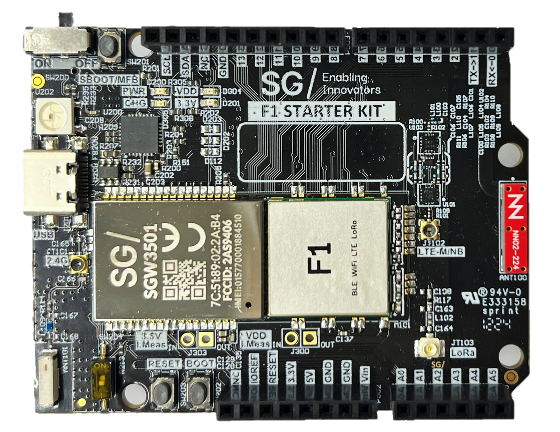
F1 Starter Kit
Varieties
Based on the cellular technologies and region, there are 4 varieties of F1 Starter Kit:
F1 Starter Kit NA, CAT-M1 (SGW3501-EVK-NA-CATM1-8130D)
F1 Starter Kit EU, CAT-M1 (SGW3501-EVK-NA-CATM1-8130D)
F1 Starter Kit Global, CAT-M1 (SGW3501-EVK-NA-CATM1-8130D)
F1 Starter Kit Global, NB-IoT (SGW3501-EVK-NA-CATM1-8130D)
Each Starter Kit comes with the following:
F1 EVK
CAP/T sensor
1-hour consultation
What Makes the F1 Starter Kit Unique
The F1 Starter Kit has four wireless protocols on a single board:
Wi-Fi for high-bandwidth local connectivity
BLE for low-power device interactions
LTE for reliable cellular communication
LoRa for long-range, low-power wide-area networking
Many connectivity decisions get made too early in development, locking you into assumptions without real-world data to back them up.
The multi-protocol approach with the F1 Starter Kit gives you the flexibility to choose the optimal connectivity solution for each specific use case, and test different protocols as your projects evolve. Need Wi-Fi for configuration but cellular for deployment? Both are right here. Want to add LoRa for remote sensors later? Already built in.
What to Expect in Development
Built with developer productivity in mind, look out for:
Arduino compatibility means your existing shields work without modifications. Same form factor, same pinout, same ecosystem you already know.
MicroPython support lets you prototype quickly without diving into Embedded C. Write readable code, iterate fast, and optimize later.
SG Ctrl Cloud Platform integration handles the device management, over-the-air updates, and data collection — everything to propel your prototype to production.
Features
Connectivity
LTE Cat-M1/NB
LoRa(WAN)
Wi-Fi 4 802.11 b/g/n standard at 2.4 GHz
Bluetooth LE
Microprocessor
Xtensa® Dual-core 32-bit LX7 Microprocessor
Up to 240 MHz
384 kB ROM
512 kB SRAM
16 kB RTC SRAM
Memory
Additional 8 MB PSRAM
Additional 16 MB NOR Flash
Peripherals
UART ×2 (one is used as USB-UART debug on Starter Kit)
SPI ×2
I2C ×2
On-board Peripherals
USB-C Device connector
USB-C OTG connector
Nano-SIM holder
Micro-SD card holder
RGB LED
Arduino UNO Shield Compatible Expansion
Up to 6 Analog Input
Up to 14 Digital IO (all configurable to PWM)
Qwiic connector
Power
Power by USB-C at 5 V
Power by VIN at 5 V
Power by Li-Ion / Li-Polymer battery at 3.7 V to 4.2 V (battery not included)
Li-Polymer Battery Connector
Battery charging and fuel gauge for accurate battery capacity measurement
Starter Kit Overview
Block Diagram
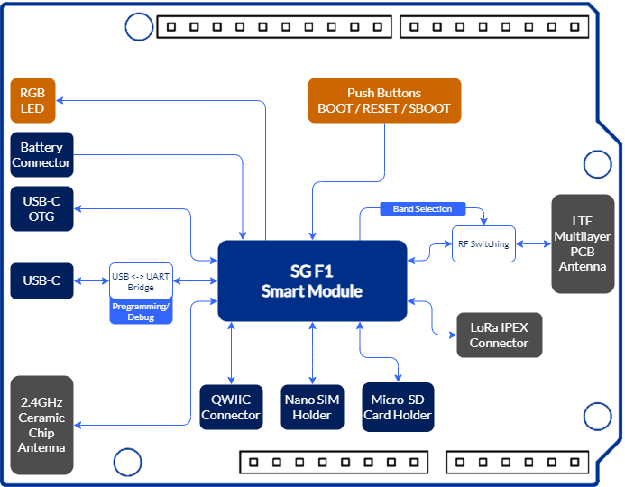
F1 Starter Kit Block Diagram
Starter Kit Topology — Top View
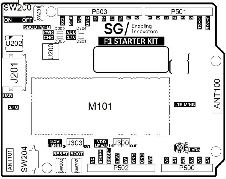
F1 Starter Kit — Top View
Major Component List (Top)
Ref. |
Description |
Ref. |
Description |
|---|---|---|---|
M101 |
SG F1 Smart Module |
D200 |
Power LED |
J201 |
16P USB-C Connector |
D305 |
Battery Charging LED |
SW200 |
Main Power Switch |
D304 |
VDD ON LED |
ANT100 |
LTE Multilayer PCB Antenna |
D201 |
3.3V ON LED |
ANT101 |
2.4 GHz Ceramic Chip Antenna |
J303 |
3.3V Current Measurement Jumper |
JT103 |
IPEX Connector (LoRa Antenna) |
J300 |
VDD Current Measurement Jumper |
SW201 |
Secure Boot Button / Multi-Function Button |
U202 |
RGB LED |
SW202 |
Boot Button |
||
SW203 |
Reset Button |
||
SW204 |
Digital IO 12 Switch |
Starter Kit Topology — Bottom View
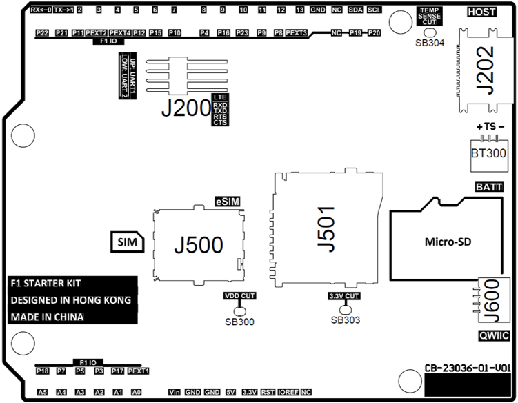
F1 Starter Kit — Bottom View
Major Component List (Bottom)
Ref. |
Description |
|---|---|
J202 |
16-P Host USB-C Connector |
BT300 |
1 mm Pitch Battery Connector |
J500 |
Nano SIM Card Slot |
J501 |
Micro-SD Card Slot |
SB300 |
VDD Shorted Jumper |
SB303 |
3.3V Shorted Jumper |
SB304 |
Battery Temperature Sense Shorted Jumper |
J600 |
Qwiic Connector |
Pinout & Pin Definitions
All IO pins on the F1 Starter Kit can be MUXed to any digital function, while P19 and P20 are connected to the I2C lane of the on-board fuel gauge.
Analog and touch inputs should only be used on analog pins.
The mechanical arrangement of the pinout is compatible with standard Arduino UNO shields.
Starter Kit Pinout Diagram – PDF
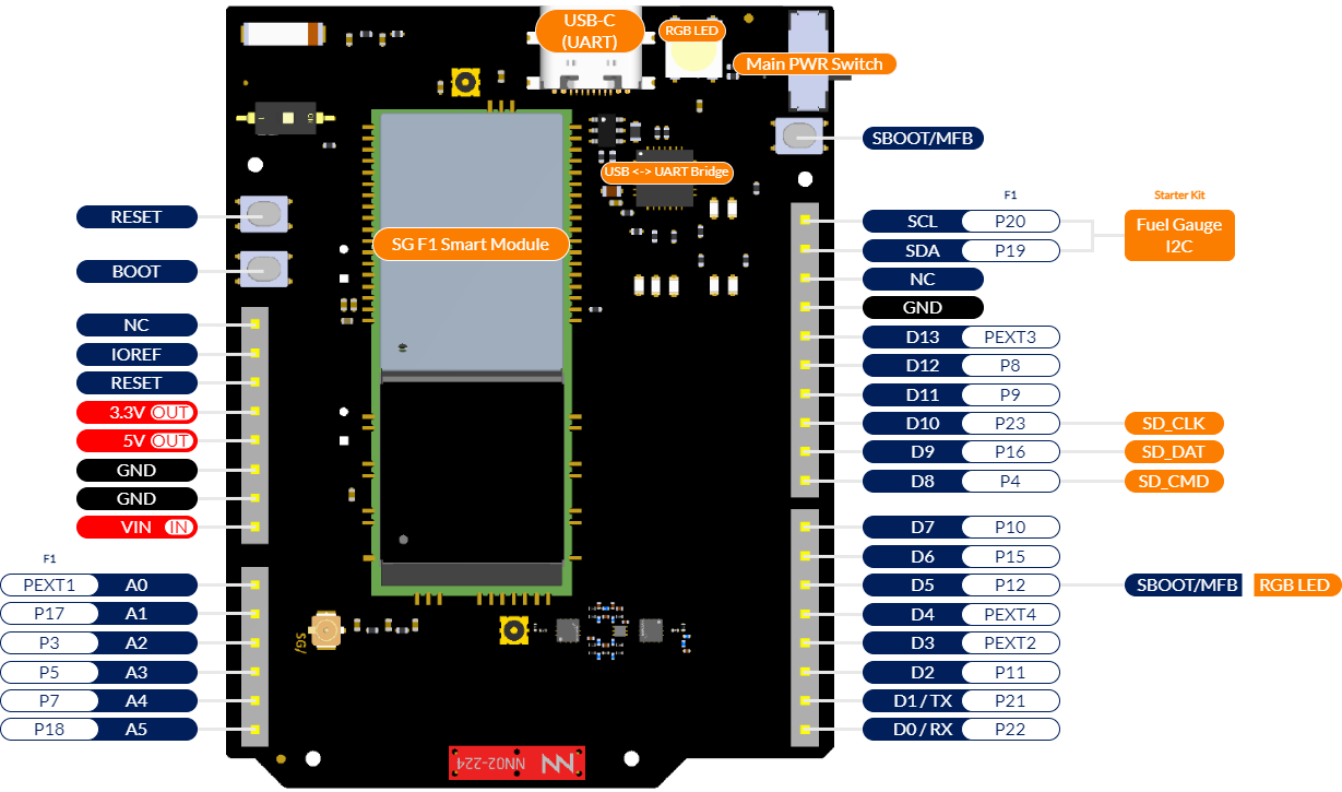
Figure 1: F1 Starter Kit Pinout Diagram
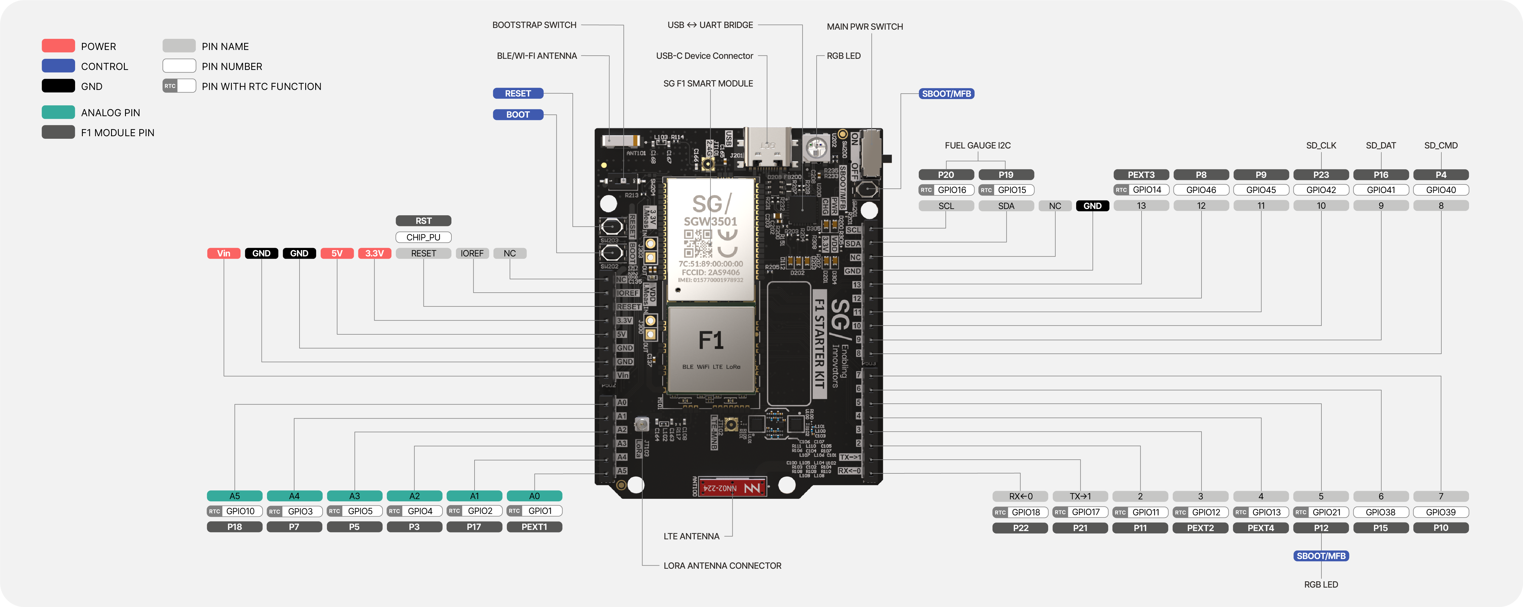
Figure 2: Top View of F1 Starter Kit
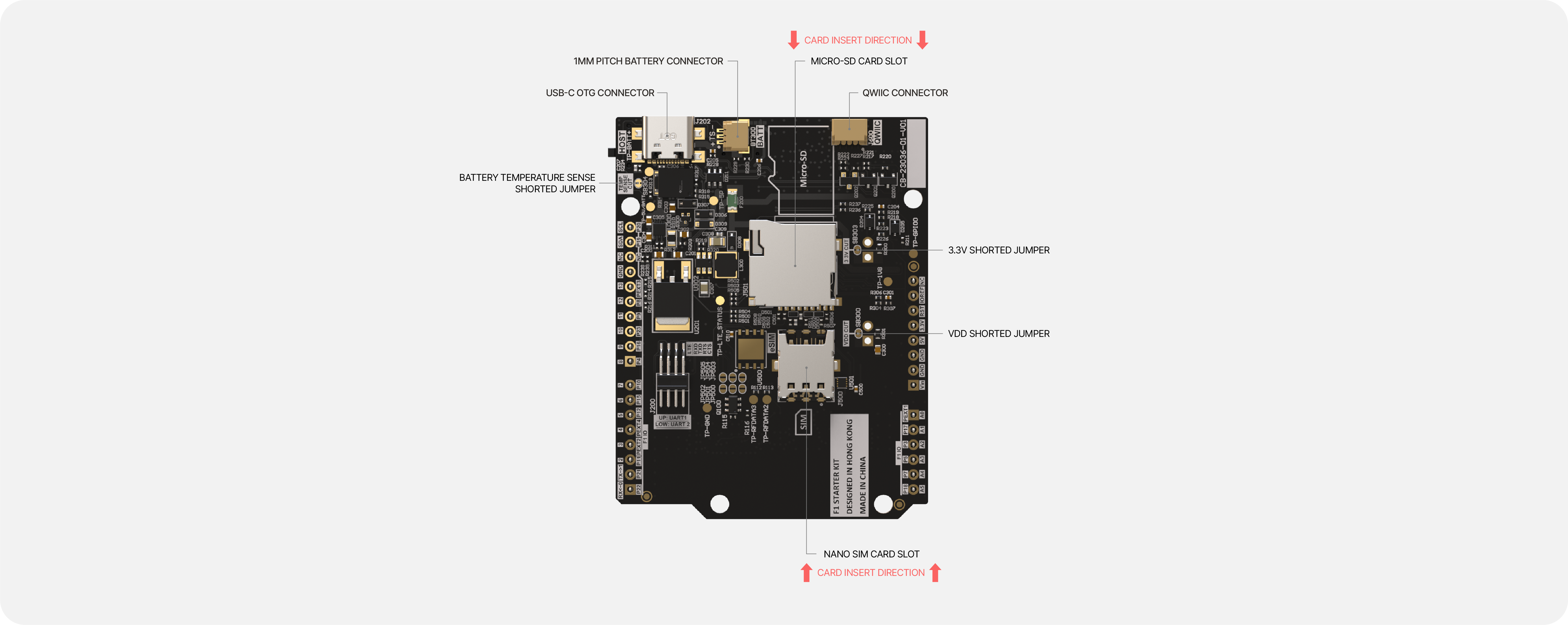
Figure 3: Bottom View of F1 Starter Kit
Pin Definitions
Table 1: Analog / Power Pin Table
Pin |
Function |
Type |
Description |
F1 Pin |
|---|---|---|---|---|
1 |
NC |
NC |
Not Connected |
/ |
2 |
IOREF |
IOREF |
Reference for digital logic — connected to 3.3 V |
/ |
3 |
Reset |
Reset |
Reset |
RESET |
4 |
3V3 |
Power |
3.3 V Power Rail |
/ |
5 |
5V |
Power |
5 V Output Power Rail |
/ |
6 |
GND |
Power |
Ground |
/ |
7 |
GND |
Power |
Ground |
/ |
8 |
VIN |
Power |
5 V Voltage Input |
/ |
9 |
A0 |
Analog |
Analog input 0 |
PEXT1 |
10 |
A1 |
Analog |
Analog input 1 |
P17 |
11 |
A2 |
Analog |
Analog input 2 |
P3 |
12 |
A3 |
Analog |
Analog input 3 |
P5 |
13 |
A4 |
Analog |
Analog input 4 |
P7 |
14 |
A5 |
Analog |
Analog input 5 |
P18 |
Table 2: Digital Pin Table
Pin |
Function |
Type |
Description |
F1 Pin |
|---|---|---|---|---|
1 |
SCL |
Digital |
I2C Serial Clock (SCL) |
P20 |
2 |
SDA |
Digital |
I2C Serial Data (SDA) |
P19 |
3 |
NC |
NC |
Not Connected |
/ |
4 |
GND |
Power |
Ground |
/ |
5 |
D13 |
Digital |
Digital IO 13 |
PEXT3 |
6 |
D12 |
Digital |
Digital IO 12* |
P8 |
7 |
D11 |
Digital |
Digital IO 11 |
P9 |
8 |
D10 |
Digital |
Digital IO 10 |
P23 |
9 |
D9 |
Digital |
Digital IO 9 |
P16 |
10 |
D8 |
Digital |
Digital IO 8 |
P4 |
11 |
D7 |
Digital |
Digital IO 7 |
P10 |
12 |
D6 |
Digital |
Digital IO 6 |
P15 |
13 |
D5 |
Digital |
Digital IO 5 |
P12 |
14 |
D4 |
Digital |
Digital IO 4 |
PEXT4 |
15 |
D3 |
Digital |
Digital IO 3 |
PEXT2 |
16 |
D2 |
Digital |
Digital IO 2 |
P11 |
17 |
D1 / TX |
Digital |
Digital IO 1 / UART TX |
P21 |
18 |
D0 / RX |
Digital |
Digital IO 0 / UART RX |
P22 |
* You may need to switch OFF SW204 when using Digital IO 12.
Board Operation
Getting Started — F1 platform setup guide
Programming References — MicroPython references for F1 platform
Additional online resources at https://www.sgwireless.com
See Getting Started for setup instructions.